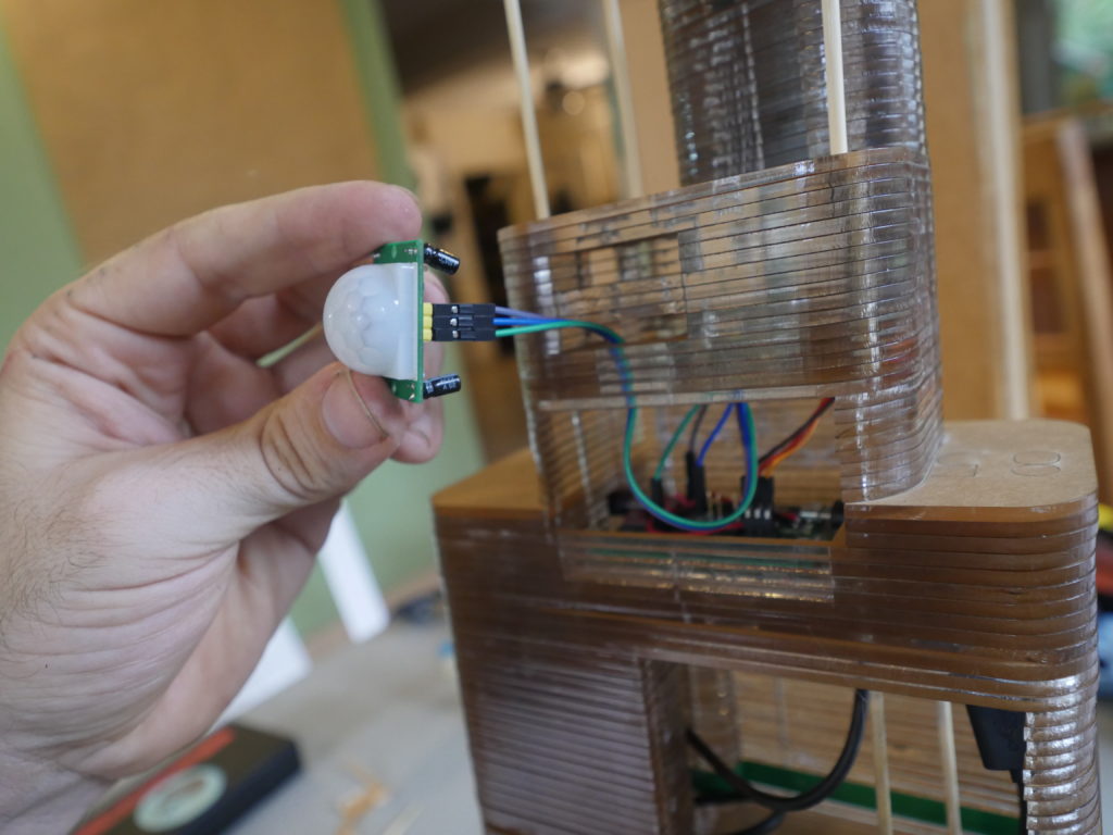
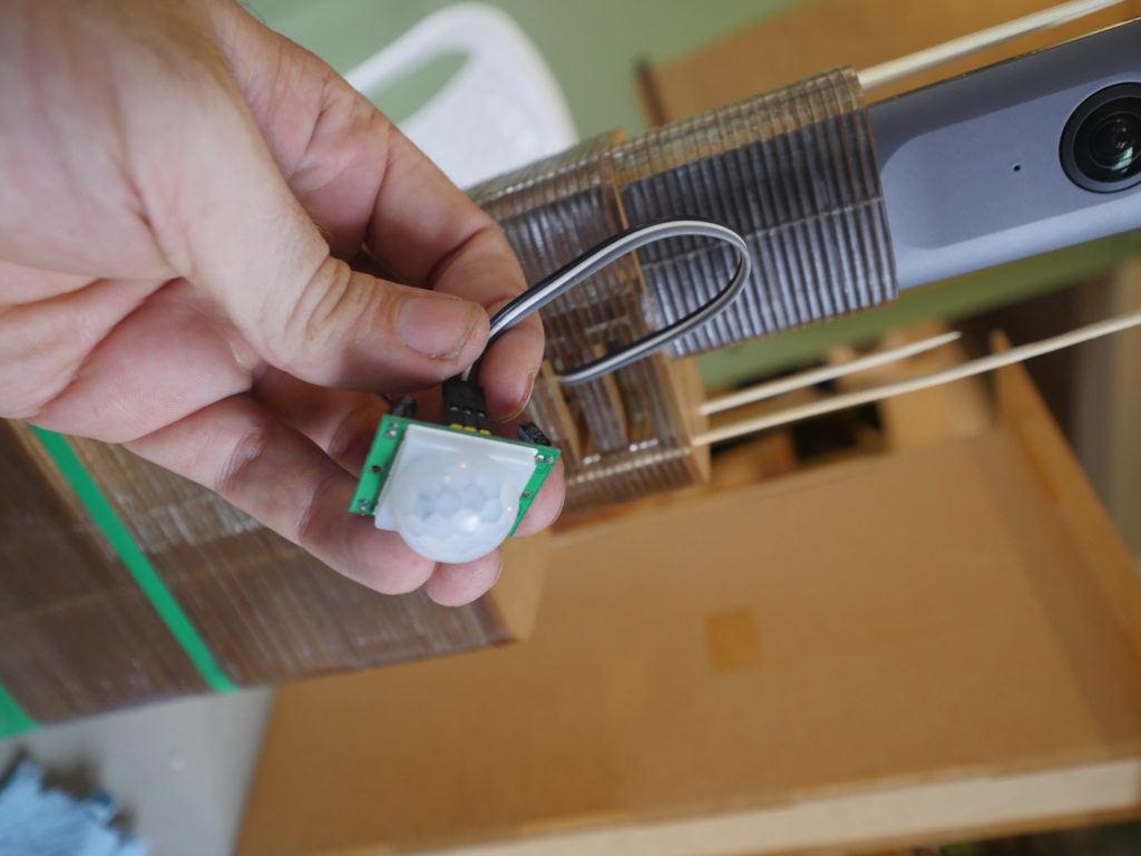
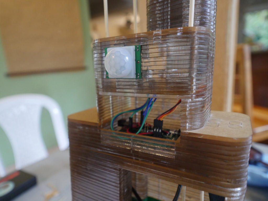
Code
Code is available in this repo https://github.com/Digital-Naturalism-Laboratories/Panatrap/tree/master/Theta_V
Hardware
Physical Designs are available here for free download: https://a360.co/2m22suQ and included in the repo
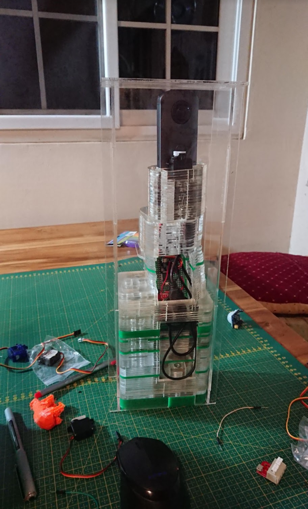
Materials
- Theta V camera (~$350 USD)
- Teensy 3.2 Arduino Microcontroller (~$15)
- USB Micro breakout board https://www.sparkfun.com/products/12035
- PIR motion detector (5V) x2
- Small Servo motor
- Proto board
- Male Header pins
- USB battery pack with On-Off Switch (~ $24)
(Specifically this one: Talent Cell 3000 mAh – https://www.amazon.com/gp/product/B01M7Z9Z1N/ref=ppx_yo_dt_b_asin_title_o01_s01?ie=UTF8&psc=1 ) - 3mm bamboo skewers (you can find these at a grocery store)
- 3mm Acrylic Sheets and Laser Cutter (preferred for this build)
OR - 3D Printer and Filament
Tools
- Acrylic Welding Glue (or Super glue)
- Soldering Iron
- Wires
Hacking Theory
The Theta cameras (and many other 360 cameras) were substantially more locked up in our attempts to remotely operate it (especially in a way that allows for long term use and have a decently quick trigger).
You can follow our detailed journey through hunting ways to control this camera here:
https://community.theta360.guide/t/usb-api-and-arduino-for-camera-trap/4758/20
Andy put in several weeks of work exploring every possible method of hacking this camera.
The camera runs android, and has an accessible USB Api (to recieve PTP commands) and in theory has all the abilities to remotely A) Turn ON/OFF and B)Trigger a Photo Capture. But the firmware blocks some of these features (even if you switch into developer mode).
Turning On/OFF
It’s tough to turn this camera on. Two ways we have found to hack it on are:
-When you send a fake keyboard command through an OTG cable
or
-When a connected Raspberry Pi boots up (unfortunately this is too slow to work as a camera trap)
Luckily we discovered that sending an emulated Keyboard command (through something like a Teensy Arduino 3.2), can remotely wake up the camera (even though this feature is not documented anywhere!), and then we just need to trigger the photo.
Triggering – Servo Style
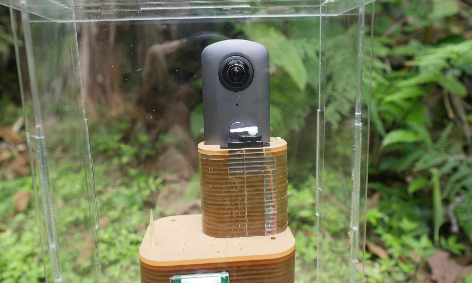
The photo triggering is then done by a small servo connected to the Arduino which manually taps the shutter button of the camera. The servo is shut down in between photos to reduce power consumption.
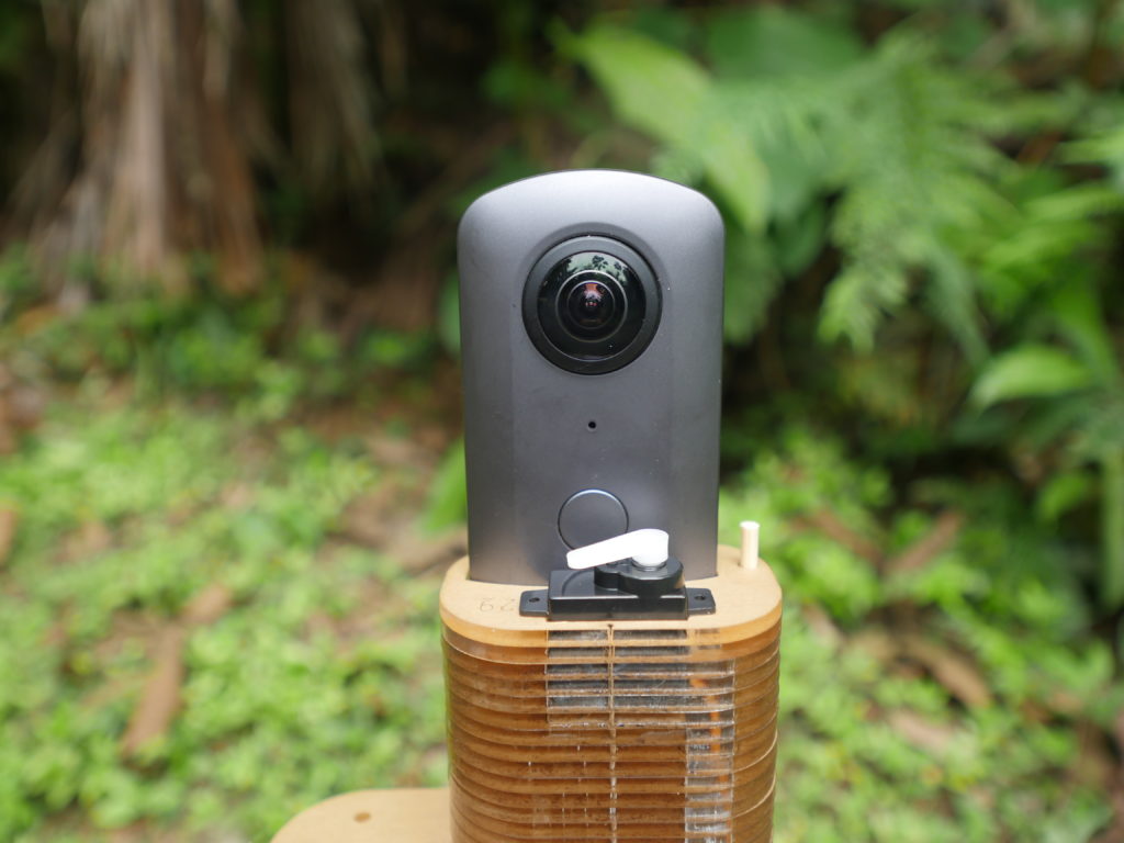
We tried a zillion other ways to remotely trigger this camera, but none will work unless the camera is already turned on manually and set into “Plugin Mode”
Build Process
Create Circuit Board
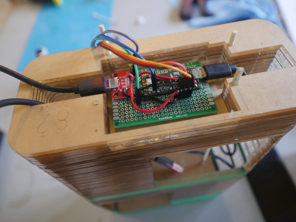
The circuitry is decently simple for this build. You have two inputs (the 2 PIRs), 1 servo, and a USB breakout you need to connect to the TEENSY 3.2
Solder some headers down the right side of your teensy.
Create extra V+ and GND
Solder a wire to the Vin ( second from the top right pin of teensy) and run these to a space where you can have at least 4 more voltage out pins on the proto board
Solder a wire to the GND (third from top right of teensy), and run these to a separate space where you can have at least 4 more GND pins to plu in the servo, PIRs and USB breakout
Connect peripherals
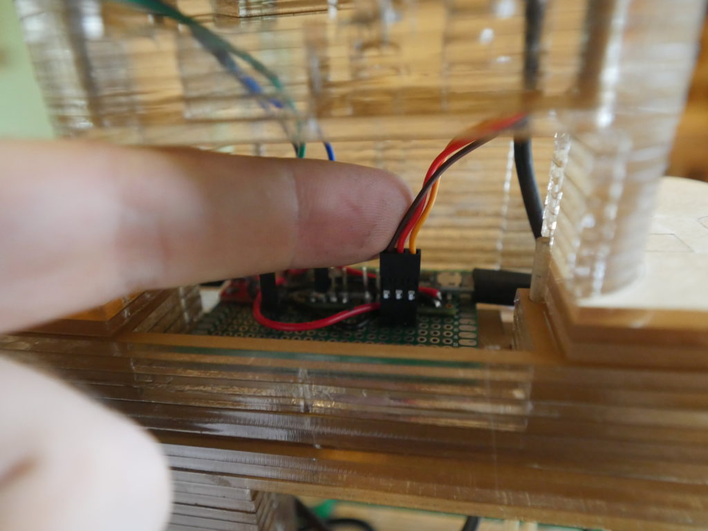
Servo: Solder 3 male header pins and attach one side to Vin, one side to GND, and the center pin to the Servo pin in your code
PIR x2 : Solder 3 male header pins and attach one side to Vin, one side to GND, and the center pin to the Servo pin in your code
USB breakout: Solder the VCC to the Vin, and the GND to the GND on the teensy
Program the Board
Code is available in this repo https://github.com/Digital-Naturalism-Laboratories/Panatrap/tree/master/Theta_V
You can upload this code for a quick easy way to help debug all the parts
/*
  PanaTrap - Theta V
  Debug Code for the turning the Ricoh Theta V camera
  into a remotely controlled,
  PIR triggered, Camera Trap
  Using the Teensy 3.2
  This camera is unfortunately blocked in lots of parts of its API from being able to just control with digital signals
    so we control it two ways
    Wake up: Sending a Fake Keyboard Command
    Take Photo:
    Trigger a servo to physically press the button
    Note: if the button is held down WHILE the camera is waking up, it will NOT take a photo, thus there is some timing trickiness here
    Note: make sure to set the Teensy on Serial+Keyboard+Mouse+Joystick
    Note: we are using the Teensy 3.2 because it can send virtual HID signals, and it is the only one I had that was 5V tolerant (which i only had 5V PIRs)
*/

#include <Servo.h>
Servo myservo;
// create servo object to control a servo
// twelve servo objects can be created on most boards

int offpos = 160;
int onpos = 180;


//Front PIR motion sensors
int fPIR = A5;
int fPIRval = -1;
int fPIRpower = 22;
int fPIRgnd = 20;

//Back PIR motion sensors
int bPIR = A2;
int bPIRval = -1;
int bPIRpower = 19;
int bPIRgnd = 17;

//LED for debugging display
int led = 13;

int detectionThreshold = 600; // Our PIRs are actually just binary, but setting up infrastructure in case other sensors are used
void setup() {
  //Serial for debugging PIRs
  // initialize serial communication at 9600 bits per second:
  Serial.begin(9600);
  digitalWrite(led, HIGH);

  //Configure the mouse (im not sure we actually have to do this
  Mouse.screenSize(1920, 1080);  // configure screen size


  //Setup Servo and put it into waiting position
  myservo.attach(23);
  myservo.write(offpos);
  delay(1000); // You have to wait before detaching the servo for it to actually move into position
  myservo.detach();


}


void loop() {

  fPIRval = analogRead(fPIR);
  bPIRval = analogRead(bPIR);
  // print out the value you read
  Serial.print("   Front PIR:  ");
  Serial.print( fPIRval);
  Serial.print("    rear:  ");
  Serial.println(bPIRval);
  Serial.println( analogRead(A3));


  //For the debug code we are just gonna run a simple routine, Field code should have timeouts, and all kinds of other stuff
  if (fPIRval > 600 || bPIRval > 600) {
    critterDetected();
  }

  delay(1);        // delay in between reads for stability
}

//For our Debug code, we are going to just Turn the camera on, and take two photos, or
//conveniently, if we are in Video mode, we will start and stop a video

void critterDetected() {
  Serial.println("Critter detected");
  //Turn camera on
  onOffCamera();

  //Take a photo
  takePhoto();
  takePhoto();

  //TODO: Wait to see if other critters still around
  //before we shut off camera

  //The theta cannot turn off, just turns on
  //It is set to go to sleep after 3 mins, so we just leave it on in case we catch another critter
  //onOffCamera();

}

void onOffCamera() {
  Serial.println("cameraONOFF");
  digitalWrite(led, LOW);

  //Wake the Camera with a Pulse
  Mouse.set_buttons(1, 0, 0);
  myservo.attach(23);
  myservo.write(offpos); // This keeps the camera from just swinging to a random position
  //Wake the Camera with a Pulse

  delay(50); // Wait for a quick click
  Mouse.set_buttons(0, 0, 0);


  //Let camera wake up
  delay(900);

  ///Chill
  digitalWrite(led, HIGH);
}


void takePhoto() {
  Serial.println("Take photo");
    myservo.attach(23);
   myservo.write(onpos);
delay (1200);//hold for like 1.2 seconds

  //Take a photo
  digitalWrite(led, LOW);    // turn the LED off by making the voltage LOW

//Set back to resting mode
    myservo.write(offpos);
   delay(200); //Need a delay or else it detaches before it finish moving
    myservo. detach();


  ///Chill 4 secs // Camera needs 4 seconds to process between photos
  delay(4000);
 digitalWrite(led, HIGH);
}

void togglePhotoVideo() {
  Serial.println("cameraTogglePhotoVideo");

  //2 second press
  digitalWrite(led, LOW);

  delay(2000);

  ///Chill
  digitalWrite(led, HIGH);

  delay(2000);

}
Create Housing
If using a 3D printer, use the model provided above, and print it out!
If using a Laser cutter, Cut out the housing pieces (auto-generated from the model by Autodesk’s slicer program)
Assemble
Stack all the slices together, and use the bamboo skewers to hold them together temporarily.
Make sure all your components fit! (or else you might need to dremel some modifications like i did here)
Next you might want to hot glue the circuit board in place.
Now use Female-female jumper wires to connect your PIR sensors to the header pins you installed.
Connect the Servo wires directly to the 3 pin header you installed
If everything looks good, connect the battery pack power to the USB breakout, and the OTG cable to the Theta Camera. Now connect the final USB from the teensy to the OTG cable. Test and see that it all works!
If everything looks good, you can superglue the stacks together. I leave the bamboo skewers in to make sure they are aligned perfect. I use acrylic weld, which works better than superglue, but it is all ok, the superglue will just leave some marks.
Weather Shield
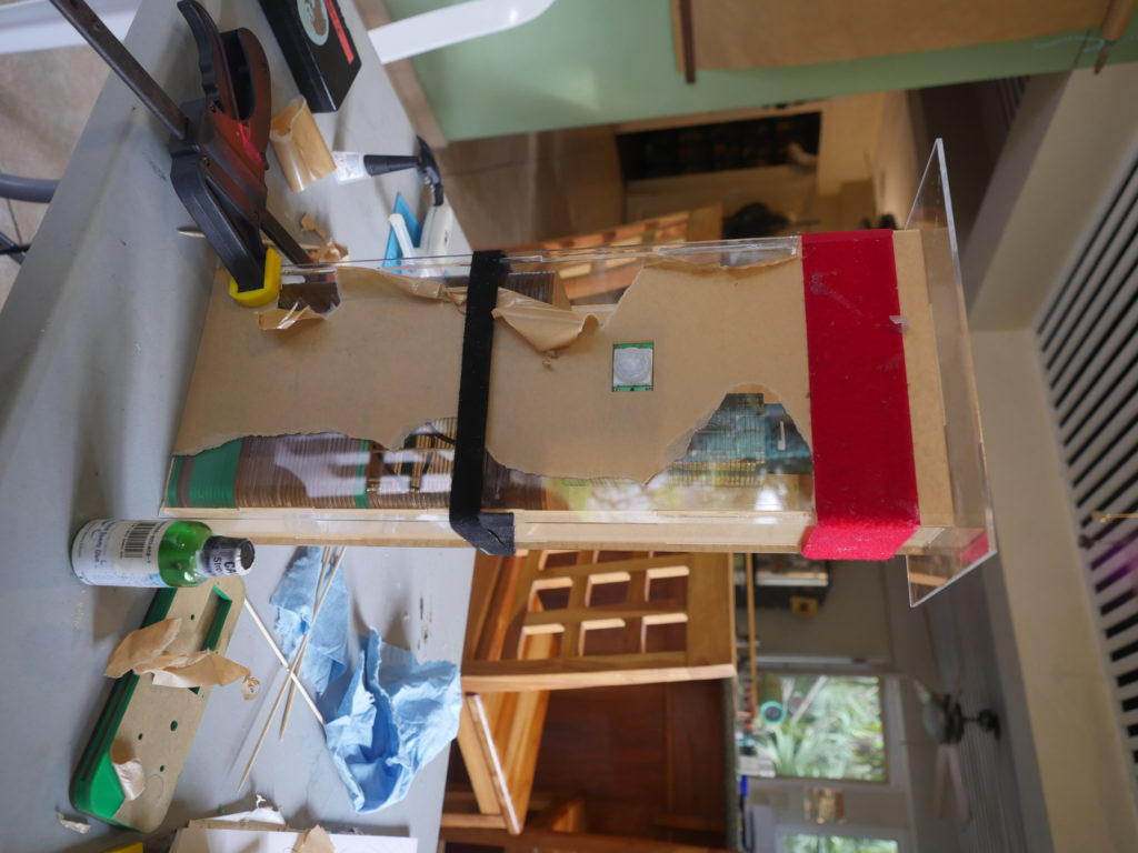
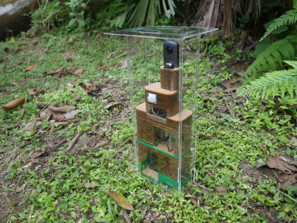
The final part of the housing will be to glue together the weather shield. This is just a big clear plastic box with a roof and some spaces to let the PIR motion detectors look through.
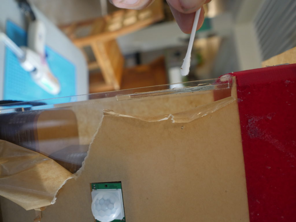
For the weather shield you want this to be as clear as possible, so i leave the protective film on the acrylic as long as possible, and just try to just the acrylic weld with a q-tip. You want to clamp and holder everythign in place. I used some velcro straps and some clamps. Let it sit for an hour at least.
Deploy
Now your device should be ready to be set out in the forest, waiting for interesting creatures to come by!
Future Development
This design is large and durable, but a bit bulky. Future designs and slim it down, and allow for more mobility.
Our DIY weather shielding works great, but it does leave a large gap between the camera and the shield which can cause glare and reflections and cut down on some of your POV.

